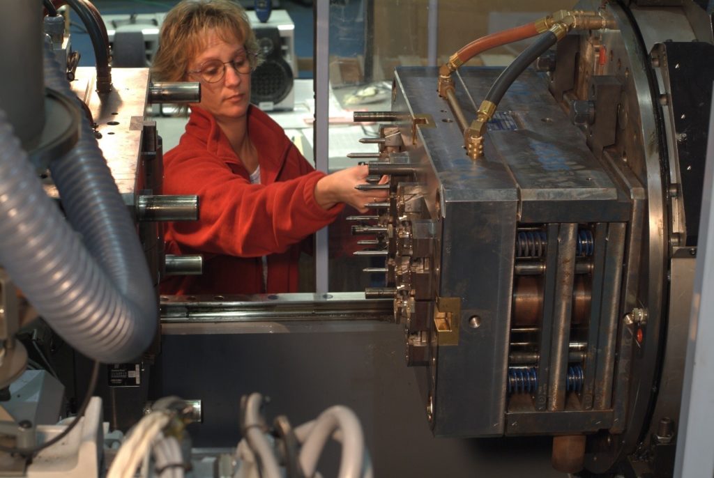
A properly designed and fabricated plastic injection molding tool is a foundational prerequisite to successfully creating an injection molded part. “Tool” or “mold” refers to the part specific capital asset used to produce plastic components. Made from tooling specific grades of steel and aluminum, they provide a negative cavity space into which molten plastic is injected to form a part.
As an integral piece in determining how a part is gated, processed and ejected, tooling has a profound impact on running components effectively and within specification. Fabricating a new mold can often come with significant capital investment and lead times. New tools can be sourced from a variety of shops in different geographic areas which offer cost models and specific skill sets that can be strategically leveraged.
TOOLING STRATEGY
Identifying an appropriate tooling strategy for a project’s technical and logistical needs is critical to the smooth implementation of a new molded product. Before making an investment in a production mold, new part designs generally begin with some level of prototyping to satisfy low volume verification activities. Common prototype methods used for molded part designs include 3D printing, machining, cast urethane or prototype injection molds depending on a mix of part design and functional testing needs. Once a part design is stable, investments in production injection molds can yield higher quantities of parts at a reduced part cost.
The requirements of a particular project and part need to be considered when specifying the type of injection mold to quote. In many cases the complexity, associated cost and lead time to build a tool can be catered to meet customer’s needs. Decision factors include how many parts need to be produced off of the tool, as well as the likelihood of future design changes that could impact tool obsolescence.
When considering a fully mature part design with a high annual usage it may be appropriate to specify multi-cavity tooling rated to last millions of cycles and built to promote production efficiency with lower part costs. Parts that are not ready for this level of tooling investment would be more suitable to quote with lower rated production, or even prototype tooling. In some cases a phased approach of building prototype tooling for limited use prior to upgrading to production quality tooling helps reduce risks associated with parts that need to be field-proven.
TOOL FEATURES
It is useful to understand some of the basic features of injection mold tooling and how they are utilized to facilitate part production.
- Stationary A-Side or Cavity Half: The non-moving side of the tool typically attached to the side of a molding machine where molten plastic is injected from.
- Moving B-Side or Core Half: The portion of the tool attached to the side of a molding machine that opens and closes against the stationary mold half. The B-side opens when a part is cooled and ready to remove from the tool.
- Cooling Lines: A network of channels made inside of the molding halves that a cooling media is flowed through to control the cooling characteristics of the plastic after it has been injected into the tool.
- Ejector System: Moving components (often pins) typically on the B side of the tool that are driven forward after mold opening to strip the cooled part off of the tool for removal.
- Sprue/Runner: A plastic flow path that allows the press to inject material into the part cavity. This can be designed to solidify and be removed with the part at each cycle or to stay molten inside of the tool.
- Tooling Actions: Moving components in the part cavity that allow for the formation of undercuts in part geometry that otherwise couldn’t be released by the single direction opening of the A and B tooling half.
TOOL CREATION
Injection molds are built by highly skilled toolmakers trained in the techniques of designing and fabricating tooling. This includes all facets of how the tool will fit into the production mold machine, as well as how the tool interacts with the part.
Reviewing and approving the mold design for fabrication is an important milestone in a tool build as it establishes several irreversible factors that can impact the quality of parts made off of the mold. Items such as how parting lines are formed, gate location and ejection location are often approved by the original part designers. Running a moldflow analysis is sometimes required prior to this stage of tooling to inform designers and toolmakers about proper gating.
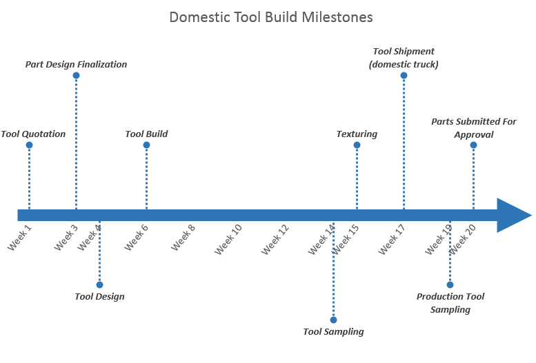
Once a tool design has been approved the toolmaker begins fabrication to a production schedule that ends at an initial or “T1” sampling. Tool delivery schedules are usually based on timing to these first shots and can range from 2 – 16 weeks based on the complexity and size of the tool build.
At the T1 sampling the molder and toolmaker work to produce parts that demonstrate the tool functions as intended. Ideally this is done with a limited number of shots in the production resin. This also represents the first opportunity to yield production-like samples off of the tool, which is often useful for verification testing and form/fit tests.
Once T1 samples are deemed acceptable, the toolmaker makes any required corrections to the tool and begins the process of polishing and/or texturing the aesthetic cavity surfaces to the designed specification. This a 1-2 week process, after which the mold is sampled again by the toolmaker to produce samples for texture acceptance.
Many texturing options are available to choose from including standard polish and grain finishes, as well as more specific patterns depending on the aesthetic intent of the part. Texture houses who apply these finishes to tooling can provide plaques showing texture options to choose from.
Once T2 samples are approved the tool can be approved for release to the molder’s production facility.
At the production facility the mold can be placed in the intended production press where a process is developed to make final in spec parts. This activity can vary in complexity based on the qualification and acceptance criteria of the product.
This typically starts with a series of scientific molding studies that identify the baseline input conditions the tool runs well with. If specific part characteristics need to be understood and controlled more specifically design of experiment (DOE) trials can be run to isolate specific process inputs and their impact on those characteristics. By using these techniques to identify low, nominal and high process settings, molders can validate a processing window to operate within that produces parts to specification.
Once the tool, process, and parts are accepted for production, the tool enters into regular production scheduling and maintenance to keep it running smoothly throughout its life. Over time the tool is monitored for signs of wear that may need corrective action to keep it running successfully. If at any point the production part made by the tool undergoes engineering changes the tool will be evaluated to see if and how it can be modified to make the part to the new specification.


